MM-wave Modular Quasi-Optical Test Bench
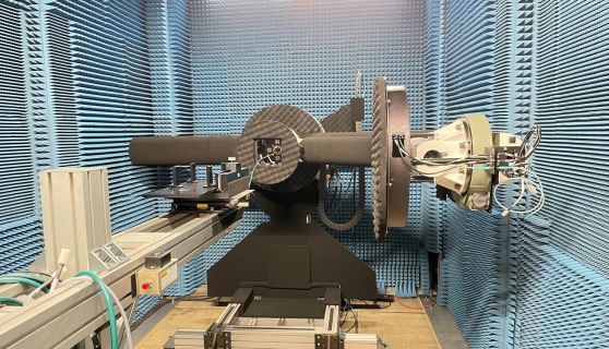
The first of these systems uses a powerful state-of-the art Vector Network Analyser (VNA – Keysight PNA-X shown in above figure) working with a Quasi-Optical (QO) circuit. The VNA is a sophisticated generator and receiver of ultra-phase-stable, coherent, finely-tunable electromagnetic radiation. It can generate as well as detect, the amplitude and phase of radiation having frequencies up to 500 GHz, with a capability to rise to 1 THz. The QO circuit is a train of special beam-shaping mirrors that treat the sub-mm wave power as if a beam of light. The QO configuration shown above offers a focusing system that concentrates sub-mm wave power into a reaction vessel producing very high power densities at energies chosen to excite specific chemical bonds.
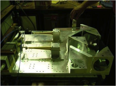
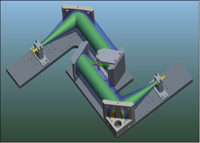
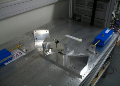
The Modular Quasi-Optical Test Bench is a flexible test system, which can be easily reconfigured enabling multiple circuit setups. Varieties of configurations can be achieved using different quasi-optical elements, such as:
• Corrugated horns
• Grid polarisers
• Focusing reflectors
• Flat reflectors
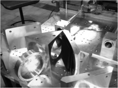
The figures below show examples of QO bench configurations that can be realised for particular EM studies in the mm and sub-mm wavelength range.
The Quasi-Optical Test Bench has been designed to perform different measurements. Among them:
- Dielectrometry from 50–325 GHz and, in association with the Rutherford Appleton Laboratory, extendable to 600 GHz
- Diffracted Gaussian Beam Analysis (Spatial Spectrum Analysis)
- Analysis of dichroic, filters and active FSS in mm-wave
Back to Antenna Measurement Laboratory.