Antenna Metrology Theory and Applications
As well as having high quality antenna measurement facilities, the group undertakes research into microwave and millimetre-wave antenna metrology. This research is focused around the major antenna measurement facilities of the Antenna Measurement Laboratory, consisting of:
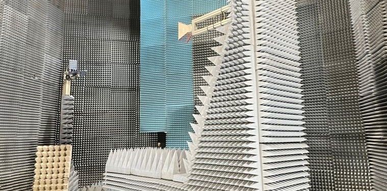
- two compact antenna test range operating from 5 GHz to 300 GHz;
- fully-screened anechoic chamber for mobile communications antenna applications (750 MHz to 5 GHz);
- NSI Planar near-field range operating to 100 GHz;
- A 9 m x 3 m x 3 m anechoic chamber for feed measurements and general measurement use;
- A NSI-700S-360 Spherical Near Field antenna measurement system housed in a purpose built anechoic chamber 4.4m long, 3.1m wide and 3.1m high and operating at frequencies up to 500 GHz.
A significant amount of our antenna metrology research is published in the following books:
-
‘Principles of Planar Near-Field Antenna Measurements’, S. Gregson, J. McCormick, C. Parini, IET Electromagnetic Wave Series, 2007, ISBN 978-0-86341-736-8. https://digital-library.theiet.org/content/books/ew/pbew053e. A comprehensive text covering the theory and practice of planar Near-field antenna measurement.
-
'Theory and Practice of Modern Antenna Range Measurements - 2nd Expanded edition in two volumes', c. Parini, S Gregson, J. McCormick, D. van Rensburg, T. Eibert, IET Electromagnetic wave series, IET , 2020, ISBN 978-1-83953-126-2 & ISBN 978-1-83953-128-6. https://shop.theiet.org/theory-and-practice-of-modern-antenna-range-measurements-2nd-edition-2. Provides a comprehensive introduction and explanation of both the theory and practice of all forms of modern antenna measurements, from their most basic postulates and assumptions, to the intricate details of their application in various demanding modern measurement scenarios.
Some of our Antenna Metrology research is illustrated by the following activities.
Mathematical Absorber Reflection Suppression (MARS)
Stuart Gregson & Clive Parini
This mathematical post-processing technique can be deployed to antenna pattern data taken using a far-field or CATR facility using only a single great circle cut to efficiently correct far-field, frequency domain data. Reflections in a CATR can often be the largest source of measurement error within the error budget of a given facility. This mode orthogonalisation and filtering technique requires only a minimum amount of information about the AUT and measurement geometry, and is able to suppress reflections in a direct far-field one-dimensional antenna range measurement.
Contrary to usual antenna measurement practice, the MARS technique deliberately displaces the AUT from the centre of rotation on the turntable. This has the effect of making the differences in the illuminating field far more pronounced than would otherwise be the case, and it is exactly this greater differentiation that makes their identification and subsequent extraction viable. Once the far-field great circle pattern cut has been acquired in this displaced condition, the AUT pattern can be mathematically translated back to the origin of the measurement co-ordinate system and from this, the equivalent cylindrical mode coefficients (CMCs) can be deduced from the measured fields.
The cylindrical mode coefficients for the, now ideally centrally located, AUT are then recovered, so any mode representing fields outside the ideal conceptual minimum MRE can be filtered out, thereby removing contributions that are not associated with the AUT. As these transforms and their inverse operations can be evaluated with the fast Fourier transform (FFT) this makes the F-MARS algorithm very efficient in terms of computational effort.
To demonstrate the method, repeat measurements were taken of the far-field great circle azimuth cut of a medium gain X-band corrugated horn in the QMUL CATR (see figure 1 below), where a single parametric change was introduced into the measurement. This change consisted of introducing a 0.6 m by 0.6 m flat reflecting plate into the chamber that was located in the same horizontal plane as the AUT, and was chosen as it constituted a worst-case configuration, as the specular reflection of the main beam of the corrugated horn directly illuminated the CATR reflector. Figure 2 below shows the great-circle far-field co-polar amplitude and phase patterns of the AUT, where the reference trace was taken without the reflecting plate. Conversely, the measured trace was taken with the reflecting plate installed within the chamber and clearly shows the effects of the additional scattering as an additional large amplitude side-lobe at around 50°.
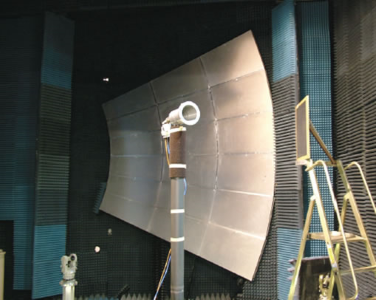
Figure 1: corrugated horn in the CATR facility.
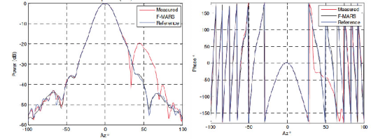
Figure 2: Power and phase patterns for the corrugated horn.
From inspection of the F-MARS processed patterns, it can be seen that the effects of the spurious scatterer have been effectively suppressed in both the amplitude and phase plots. Details can be found at:
Poly-Planar Near-Field Measurements
Stuart Gregson & Clive Parini
Conventional single cut planar near-field measurements are restricted to high-gain antennas and to radiation pattern angles covering much less than the forward hemisphere, due to the truncation of the extent of the planar surface that the radiation fields are measured. We have developed techniques to combine several near-field planar scans to calculate the far-field radiation pattern of a given AUT, to much wider angles, and indeed full spherical coverage.
As an example, we demonstrate a poly-planar technique in which the AUT is mounted in one of six discrete orientations, these orientations being the positive and negative directions of the three orthogonal positional axes. This cubic geometry is the most demanding case, as the orthogonality between adjacent partial scans would constitute a worst case scenario whilst being relative simple to realise. Using our NSI planar scanner and the corrugated horn (shown in Figure 3) as the AUT, all six surfaces of the cube surrounding the AUT were sampled by performing the following rotations from position:
- AUT nominally aligned to axes of range;
- positive rotation of 90° about y-axis;
- negative rotation of 90° about y-axis;
- positive rotation of 180° about y-axis;
- positive rotation of 90° about z-axis, followed by a positive rotation of 90° about new x-axis;
- positive rotation of 90° about z-axis, followed by a negative rotation of 90° about new x-axis.
The requirement for the inclusion of the back plane follows from the requirement to perform the pattern integration over a closed surface. When the partial scans were completed each of the six partial scans were processed using our transformation algorithm. The y-polarised electric near-field can be found plotted below and as expected, the fields at the intersection between adjacent partial scans are continuous.
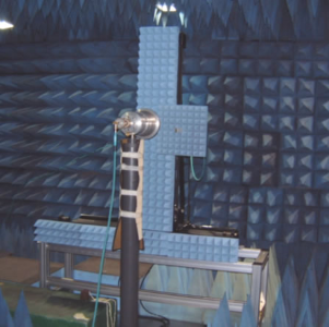
Figure 3: Corrugated horn and the NSI near-field scanner.
These cubic data sets were subsequently transformed to the far-field and resolved onto a Ludwig III polarisation basis. An example pattern is shown below, where the blue trace represents patterns obtained from the poly-planar technique, whilst the red trace denotes results obtained from our compact antenna test range (CATR). The high frequency oscillatory behaviour evident within the azimuth cut of the CATR at wide angles is a result of multiple reflections within the facility and should be ignored.
Details can be found in chapter 9 of:
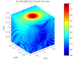
Figure 4: Y-polarised electric field for the six surfaces.
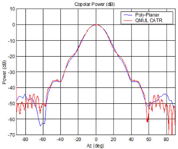
Figure 5: Comparison of far-field patterns from the Poly-Planar Near-field and CATR measurements.
Examining and Optimizing Compact Antenna Test Ranges for 5GNR OTA Massive MIMO Multi-User Test Applications
Stuart Gregson & Clive Parini
Direct far-field testing has become the baseline test methodology for sub-6 GHz over the air (OTA) testing of the physical layer of radio access networks with the far-field multiprobe anechoic chamber (FF-MPAC) being widely utilized for the test and verification of massive multiple input multiple output (Massive MIMO) systems when operating in the presence of more than a single user. The utilization of mm-wave bands within the 5th generation new radio (5GNR) specification has necessitated that since the user equipment should, preferably, be placed in the far-field of the base transceiver station (BTS) antenna, excessively large FF-MPAC test ranges are required or, alternatively the user equipment is paced at range-lengths shorter than that suggested by the classical Rayleigh criteria. However, contrary to this, a recently proposed solution involves the use of a novel Parabolic Toroid Compact Antenna Test Range (PT-CATR). This is especially well suited to the needs of 5G OTA testing and we have quantitatively verified its success by assessing the measurement of common communication systems performance metrics.
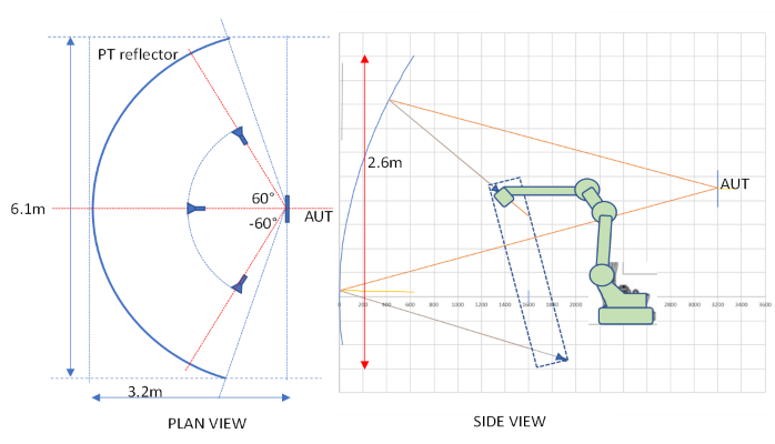
Figure 6: Left: Azimuth geometry of full PT CATR for full +/-60° of horizontal scan. Right: side view of system with robotic arm providing feed movement that gives +/-15° beam scanning in vertical plane.
- S.F. Gregson; C.G. Parini, "Examining and Optimizing Compact Antenna Test Ranges for 5GNR OTA Massive MIMO Multi-User Test Applications",2020 Antenna Measurement Techniques Association Symposium (AMTA)
- S.F. Gregson, C.G. Parini, “A Parabolic Torus Compact Antenna Test Range for 5G NR Massive MIMO OTA Multi-User Test Applications”, IEEE International Symposium on Antennas and Propagation and North American Radio Science Meeting, 5-10 July 2020, Montréal, Québec, Canada.
Examining and Optimising Far-Field Multi-Probe Anechoic Chambers for 5GNR OTA Testing of Massive MIMO Systems
Stuart Gregson & Clive Parini
Direct far-field (DFF) testing has become the de facto standard for sub-6 GHz over the air (OTA) testing of the physical layer of radio access networks with the far-field multi- probe anechoic chamber (FF-MPAC) being especially widely deployed for the verification of massive multiple input multiple output (Massive MIMO) antennas in the presence of several users. The adoption of mm-wave bands within the fifth generation new radio (5G NR) specification has meant that, as these systems require the user equipment be placed in the far- field of the base transceiver station (BTS) antenna, either excessively large FF-MPAC test systems are required or, the user equipment is paced at range-lengths very much shorter than that suggested by the classical Rayleigh criteria. In this work we explored range length effects on several communication system figures of merit and examines the consequences of testing within smaller enclosures. Resulting the the Variable Far-Field Distance Chamber design shown below.
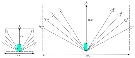
Figure 7: Variable FF distance chamber design for FF-MPAC compared with traditional FF-MPAC.

Figure 8: Effective FF distance for azimuth scan angles for the variable FF distance chamber design for FF-MPAC.
-
S.F. Gregson; C.G. Parini, "Examining and Optimising Far-Field Multi-Probe Anechoic Chambers for 5GNR OTA Testing of Massive MIMO Systems", 2020 14th European Conference on Antennas and Propagation (EuCAP)
Computational electromagnetic modelling of compact antenna test range quiet zone probing: A comparison of simulation techniques
Clive Parini, Rostyslav Dubrovka & Stuart Gregson
This work concerns an EM simulation study predicting the quality of the pseudo plane wave of a single offset compact antenna test range (CATR). We have extended our previous quiet-zone performance predictions to rigorously incorporate the effects of probing the CATR quietzone using arbitrary but known field probes. This paper compares and contrasts results obtained using plane-wave spectrum and reaction integral based simulation techniques. This investigation leads to recommendations as to the optimal field probe choice and measurement uncertainties.
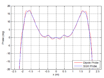
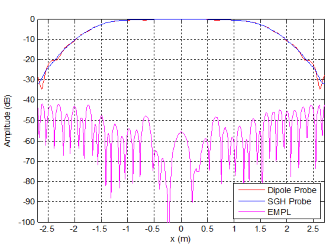
Figure 9: Simulated CATR QZ measurement using planar transmission formula.
Simulated the probed CATR QZ using a SGH probe – industry standard; Simulated the CATR QZ assuming an infinitesimal electric dipole, “theory”. SGH reduces high spatial frequency ripple
- C.G. Parini; R. Dubrovka; S.F. Gregson, "Computational electromagnetic modelling of compact antenna test range quiet zone probing: A comparison of simulation techniques", 2016 10th European Conference on Antennas and Propagation (EuCAP)