Reconfigurable Antennas, Arrays and Microwave devices
Radio Frequency (RF) communications have existed for centuries, and the frequency spectrum for these communications is an increasingly congested resource, particularly below 30GHz. As a result of this, researchers and designers in both industry and academia are looking at multiple ways to manage this congestion, whilst still maintaining the high performance demanded by consumers. Different approaches are being taken to find novel methods around the spectrum congestion. These include reconfigurable systems such as those used in Cognitive Radio, which locate available spectrum space, and reconfigure the system to operate at the available frequencies. Devices, which can intelligently shift parameters of their operation in this way, to provide optimal performance, are actively being researched.
Another approach is to move away from the congested areas of the spectrum, into the millimetre wave, Extremely High Frequency (EHF) bands. These bands not only offer less congested spectrum space, but also the opportunity for significantly more compact systems due to the short wavelengths. However, the short wavelengths present a challenge to designers, due to the increased absorption and reduced propagation range at these high frequencies. To alleviate the propagation problems, research is being carried out into reconfigurable systems which have high gain, and are able to intelligently alter the propagation direction to steer the beem around obstacles.
Reconfigurable Designs
James Kelly
Reconfigurable antennas have been in use for a number of decades, first being developed in the early 1930s. Throughout the 20th Century, research was focused on large antennas, using a range of reconfiguration techniques. Both mechanical and electronic based reconfiguration techniques were explored and this is still the focus of a lot of research. The rise in the demand for smaller, ‘connected’ devices from the 1990s onwards led to the development of designs for planar reconfigurable antennas. Many of these designs focus on the use of switches and tuning elements based around semiconductors. Those devices include PIN diodes and Field Effect Transistors (FETs). Both of which are used as switches. Research has also been undertaken, within the literature, on reconfigurable antennas incorporating Micro Electro-Mechanical System (MEMS) switches. Today there is increasing interest in smart materials to provide the reconfiguration. In the smart material approach the bulk properties of the material are varied in order to achieve reconfiguration. Examples of smart materials include: Ferro-electric and Piezo-electric materials, which change their properties based on an externally applied excitation. Other examples include: phase change materials, optically controlled organic semiconductors and liquid metal.
Programmable liquid antennas and circuits
Traditional approaches, for reconfiguring antennas, suffer from limitations, including:
- Complexity of biasing and control circuits
- Significant overall power consumption
- Poor harmonic performance
- Limited tuning range
a)
b)
Fig. 1. (a) frequency reconfigurable antenna, (b) bandwidth reconfigurable antenna.
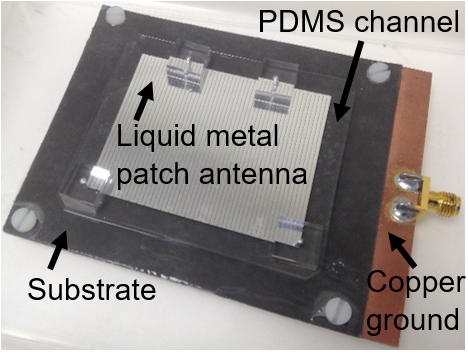
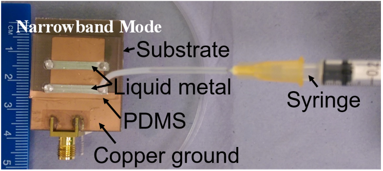
Recently new electronic materials have emerged which have the potential to address many of these limitations. For around four years, we have been exploring opportunities for creating antennas/circuits using Gallium-based liquid metal (LM). Fig. 1 shows two of the antennas that we have developed.
Millimetre Wave reconfiguration
James Kelly
Millimetre wave communication is gaining a large amount of attention, from both universities and industry. One of the key reasons that the spectrum from 30GHz to 300GHz is attractive is that the small wavelength enables a dramatic reduction in the size transceiver systems. Adding to this, there is more freely available spectrum in this band. Beamforming is a key focus of research into reconfigurable antennas operating in the millimetre wave bands and refers to the process of shaping and steering the direction of the main beam. Beamforming, also known as spatial filtering, can offer significant improvement over the use of an omnidirectional single element antenna. A beam can be formed by a linear array of antenna elements in any direction between broadside and endfire, by progressively phasing the elements of the array. This can be further developed into beam-steerable systems, which can direct the beam over a range of angles.
Hybrid antenna approaches for high performance reconfigurable mmWave antennas
Through our research (e.g. on the MILLIBAN EPSRC project) we have sought to unlock the potential of millimetre wave communications technology by addressing the urgent need for millimeter wave (mmWave) beam steering techniques that offer: high gain, continuous beam steering, wide angle steering, and low power losses. The objectives of our research on the MILLIBAN project are to:
- Develop techniques to compensate for performance degradation (e.g. beam broadening and scan loss) whilst also improving the scan angle range.
- Develop approaches for continuous beam steering having reduced power losses.
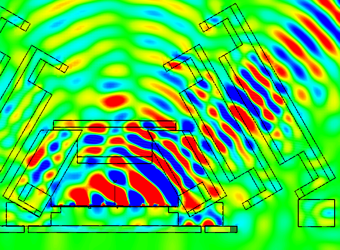
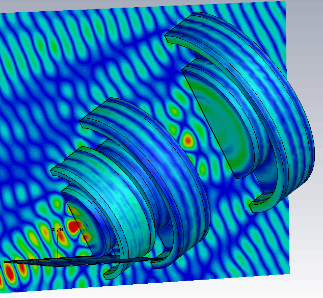
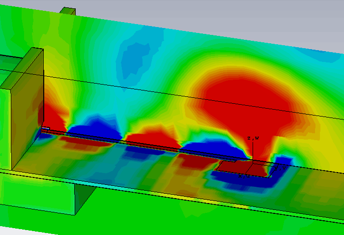
Motivated by the objectives, discussed above, we have hybridised various antenna technologies e.g.: 1) phased array and parasitic (Fig. 2), 2) phased array and lens (Fig. 3) [1], 3) phased array and transmitarray (Fig. 4) [2]. We have also developed switches (Fig. 5) [3] and phase shifters having low insertion loss at millimetre wave frequencies.
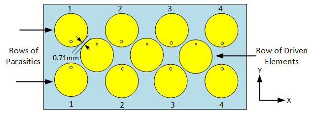
Fig. 2. Hybrid antenna employing phased array and parasitic steering in concert.
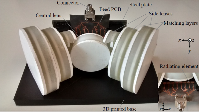
Fig. 3. Hybrid antenna employing phased array steering together with a system of lenses to mitigate for scan loss.
(a)
(b)
(c)
Fig. 4. Magnetic Field Distributions (a)-(b) showing focusing action of side lenses, (c) on single element of the phased array feed.
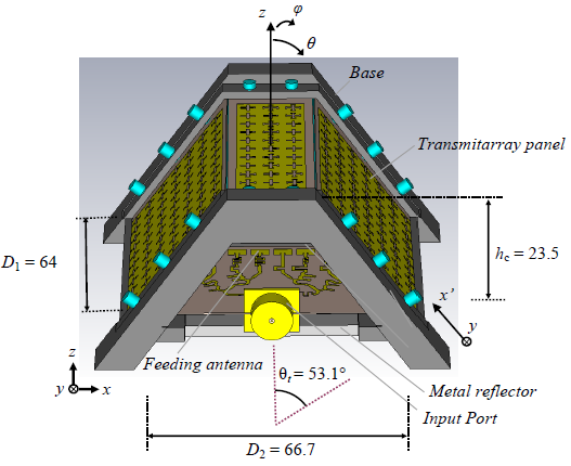
Fig. 5. Hybrid antenna employing phased array steering together with transmitarray panels to mitigate for scan loss.
Fig. 6. Single pole double throw switch incorporating removable liquid metal walls. Key: substrate = blue, copper = yellow, plated vias = red, liquid metal vias = green.
Applying Reconfigurable Millimetre wave technology
Khalid Rajab
Optically Reconfigurable Reflectarray
This system presents an optically reconfigurable reflectarray for operation at the Ka band. The Ka band has significant application for technologies such as satcom (satellite communication) and 5G millimetre-wave communications. Hence, it is important to have means of controlling the beam patterns in order to optimise communication data rates.
In order to do this, a reflectarray has been designed which uses optical reconfigurability to modify the radiation pattern. The reflectarray comprises a silver inkjet-printed array of unit cells, each designed to control phase by a specified amount. A silicon layer is optically activated through use of infrared LEDs, which provide a safe and cost-effective means of illumination, particularly in comparison to laser-based alternatives. By controlling the power density of the light incident on each unit cell, relative amplitudes can be controlled across the surface of the reflectarray, thus invoking reconfigurable non-linear arrays, such Chebyshev arrays which maximise directivity with low sidelobe levels, or Binomial arrays which have no sidelobes.
Figures 7(a) and 1(b) show a multi-layered reflectarray, along with a single inkjet-printed unit cell, respectively. The entire system was designed, fabricated and measured in the QMUL Antenna Measurement facilities at around the 30 GHz range.
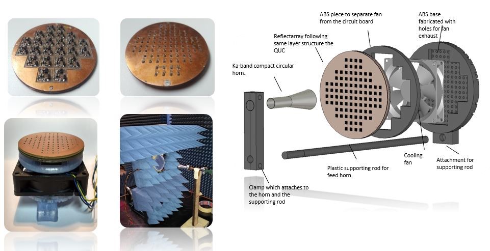
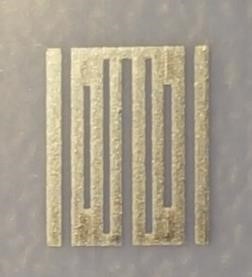
Figure 7: (a) Multi-layered reflectarray, (b) single inkjet-printed unit cell.
Short range, High data rate communications
Specific bands in the millimetre wave regions are gaining large amounts of interest. For example, in the United Kingdom, the frequency band between 57.1 and 63.9 GHz has been allocated for Fixed Wireless Systems (FWS). Given that nearly 7GHz has been reserved, this band will be able to support multi-Gbps communications such as those implemented in WirelessHD and 802.11ad (WiGig) protocols. Similar frequency allocations have taken place internationally, meaning that this band will be heavily exploited in the near future.
Millimetre-wave imaging
Another application of reconfigurable millimetre wave technology is that of imaging systems. Various applications for this technology exist, including medical, defence, security and safety purposes. The frequency of operation depends on the application, but the typical frequencies used, include: 35GHz, 94GHz, 140GHz and 220 GHz. These frequencies are used due to the comparably lower attenuation by air and moisture in these bands when compared to the other millimetre wave frequencies. This makes these frequencies applicable to imaging systems such as those used by commercial aircraft for landing in low visibility. Similarly, since these frequencies do not cause ionisation, they can be used for security imaging systems at airports to detect potentially malicious objects.
Beamformer design
Anthony Brown
Each element of an array antenna is fed by a beamformer which “weights” the elements before combining them to produce an overall radiation pattern. These weights are in general complex (that is involve both amplitude and phase). The beamformer implementation can be analogue, digital or a hybrid type. The choice of technique depends on a wide range of factors including cost, energy consumption, bandwidth and, of course the level of RF performance required.
From the performance point of view many systems have more complex radiation pattern requirements than merely steering a beam peak in a certain direction. Examples include maintaining the shape of a beam with scan angle, control of sidelobes during scanning, interference suppression by directing nulls towards interference sources [4], [5], and many others.
It is also of increasing interest to correlate between elements rather than perform straightforward beamforming. This approach can be used to improve signal-to-noise-ratio, or to adopt strategies such as MIMO or Massive MIMO.
Whatever the constraints, the requirements affect the type of beamformer and its ultimate performance. The beamformer design should not, in general, be separated from the rf design of the array. One main reason for this is that mutual coupling affects the design of both beamformer and antenna. Mutual coupling occurs in any array, to a greater or lesser extent, and results in any one element being affected by its neighbours. In some arrays this has an extremely important affect when defining the correct weights that the beamformer must provide. For example, in wide band arrays the coupling is often complex and highly frequency sensitive. If the system is required, say, to produce nulls in certain directions then the weights required will be frequency sensitive in a non-linear fashion. This has to be recognised when designing the beamformer and may mean that a digital beamformer is required in order to provide the required accuracy. Other examples, where mutual coupling is important, include random arrays or array fed reflectors.
Of equal interest is the algorithm used in the beamformer; in other words, how do you generate the required weights for a particular pattern requirement. In cases where the beamformer is only required to generate a small number of beams this could be achieved using a look-up table but when in cases where the beamformer must generate hundreds or even thousands of beams, over wide frequency bandwidth, the problem needs a much more sophisticated approach which is still a topic of active research within the community.
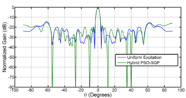
Fig. 8. Null Steering in an irregular array, comparing different algorithmic approaches [6].
Large Phased Array Calibration for Radio Astronomy
Anthony Brown
Phased array (or multiple beam) antennas have been of interest in radio astronomy for some time. Dual polarised large arrays with wide angle broadband performance present new engineering challenges.
Figure 1 below illustrates one such structure which is a proposed array for the Square Kilometre Array (SKA) undertaken by the SKA organisation (www.skatelescope.org). The array itself is an interferometer comprising 512 stations with each station having 256 elements. Each element is a dual polarised and operates over a 7:1 bandwidth. The stations deploy the elements on an irregular grid (to minimise the element count). This of course means that each dual polarised element is in a different electromagnetic environment such that understanding the mutual coupling environment becomes extremely important.

Fig. 9. The SKA Low Frequency Array (photo credit: SKA organisation, www.skatelescope.org)
The array is beamformed using a digital beamformer enabling, in principal, highly accurate calibration of each beam which is essential to high dynamic range imaging.
QMUL in collaboration with University of Cambridge are involved in addressing three key issues relating to these large arrays:
-
Computation of these very large structures to a defined accuracy. Normal commercial software is inappropriate to such large structures due to the computational resources required. We are aiming at several orders of magnitude improvement without degrading of accuracy.
-
Verification of the actual embedded element patterns (that is including all coupling) via direct measurement. Large low frequency arrays are not amenable to anechoic chamber measurements so alternative methodologies, including use of drones are being evaluated.
-
Optimal introduction of actual embedded element patterns within the digital beamformer strategy bearing in mind the mutual coupling effects change with scan angle and frequency. This effects the beamformer efficiency and the resultant image quality.
Highlights and Research Outcomes
Selected Recent Publications
-
[1] T. Hill, J. Kelly, M. Khalily, T. Brown, “Cascaded Fresnel Lens Antenna for Scan Loss Mitigation in Millimeter-Wave Access Points,” IEEE Trans. Ant. Propag., vol. 68, no. 10, 2020.
-
[2] T. Hill, J. Kelly, M. Khalily, T. Brown, “Conformal Transmitarray for Scan Loss Mitigation with Thinned Reconfiguration,” in European Conference on Antennas and Propagation (EuCAP), 2019.
-
[3] S. Alkaraki, J. Kelly, A. Borja, R. Mittra, Y. Wang, “Gallium-Based Liquid Metal Substrate Integrated Waveguide Switches,” IEEE Microw. and Wireless Comp. Lett., 2020.
-
[4] A.A Khan, A.K. Brown, “Sector Nulling in Planar Irregular Sub-arrayed Sparse Array Antennas,” IET Microwaves Antennas and Propagation, vol. 10, no. 1, pp. 25-30, Jan. 2016, DOI: 10.1049/iet-map.2014.0712.
-
[5] A.A. Khan, and A.K. Brown, “Optimisation of Scanning Difference Pattern and Monopulse Feed,” International Journal on Antennas and Propagation, 2017, DOI: https://doi.org/10.1155/2017/3869085.
- [6] A.A. Khan, and A.K. Brown, “Null steering in irregularly spaced sparse antenna arrays using aperture distributed subarrays and hybrid optimiser,” IET Microwaves Antennas Propagation, vol. 8, no. 2, pp. 86-92, Jan. 2014, DOI: 10.1049/iet-map.2013.0214.
-
[7] Quentin Gueuning, Jean Cavillot, Stuart Gregson, Christophe Craeye Eloy de Lera Acedo, Anthony K Brown, Clive Parini, “Plane-wave spectrum methods for the near-field characterization of very large structures using UAVs: The SKA radio telescope case” to be presented at EUCAP 2021, March 2021
-
[8] Iman Farhat, Alessio Magro, Mark Bezzina, Kristian Zarb Adami, Eloy de Lera Acedo, Livia Massa, Alec Josaitis, Quentin Gueuning, Alexander Pettett, Anthony Brown, Christophe Craeye, “A Novel UAV Beam Measurement System for the SKA1-LOW Telescope” to be presented at EUCAP 2021, March 2021
